The OSI Model
The OSI model is the conceptual framework that underpins all modern networking. For the CCNA 200-301 exam (objective 1.1), you must understand how data flows through the seven layers, from physical transmission to application interaction. Real network engineers use this model to troubleshoot complex issues and design interoperable systems—without it, you're flying blind.
Jump to a section
The International Shipping Company
Imagine you run an international shipping company. Your job is to get a package from a sender in New York to a receiver in Tokyo. The process involves multiple layers of service. At the top, the sender writes a letter (Application layer). Your company provides a service that accepts letters and decides to use express shipping (Presentation layer) and sets up a session with the receiver's local office to coordinate delivery (Session layer). The transport layer breaks the letter into smaller packets, numbers them, and ensures they all arrive—if one is lost, it's resent. The network layer reads the destination address and decides the route: New York to Chicago to Los Angeles to Tokyo. The data link layer takes each packet and puts it in a container (frame) with the next hop's address. Finally, the physical layer is the truck, ship, and plane that actually move the containers. Each layer only talks to its counterpart at the destination: the transport layer in New York talks to the transport layer in Tokyo, ensuring reliable delivery. If a container is damaged, the physical layer doesn't care—it just moves bits. But the data link layer might detect errors and request a retransmission. This layered approach allows you to swap out trucks for trains without affecting the higher layers, just as changing Ethernet to Wi-Fi doesn't affect your web browser.
How It Actually Works
The Open Systems Interconnection (OSI) model is a seven-layer conceptual framework developed by the International Organization for Standardization (ISO) in 1984. It standardizes the functions of a telecommunication or computing system into abstraction layers, each serving a specific purpose and communicating with its peer layer on the destination device.
Why the OSI Model Exists
Before the OSI model, vendors like IBM, DEC, and Novell used proprietary networking stacks. Devices from different vendors couldn't communicate. The OSI model provided a common language to describe network functions, enabling interoperability. While the TCP/IP model is now the de facto standard, the OSI model is still used for teaching, documentation, and troubleshooting because its detailed layering helps isolate problems.
The Seven Layers in Detail
Layer 7 – Application: The layer closest to the user. It provides network services to applications (e.g., HTTP, FTP, SMTP). It does not include the application itself, but the protocol that the application uses to communicate over the network.
Layer 6 – Presentation: Translates data between the application layer and the network. Handles encryption (e.g., SSL/TLS), compression, and data formatting (e.g., converting EBCDIC to ASCII).
Layer 5 – Session: Manages sessions between applications. Establishes, maintains, and terminates connections. Synchronization points allow recovery from interruptions. Examples: NetBIOS, RPC.
Layer 4 – Transport: Provides reliable or unreliable delivery. Segments data from upper layers into smaller units (segments). Key protocols: TCP (connection-oriented, reliable) and UDP (connectionless, best-effort). Handles flow control and error recovery.
Layer 3 – Network: Determines the best path through the network. Routes packets from source to destination across multiple networks. Uses logical addressing (IP addresses). Key protocol: IP. Routers operate at this layer.
Layer 2 – Data Link: Provides node-to-node data transfer across a single link. Frames packets from Layer 3 and adds physical addressing (MAC addresses). Detects and possibly corrects errors that occur at Layer 1. Switches and bridges operate here. Sublayers: LLC (Logical Link Control) and MAC (Media Access Control).
Layer 1 – Physical: Transmits raw bit stream over the physical medium. Defines electrical, mechanical, procedural, and functional specifications for activating, maintaining, and deactivating the physical link. Hubs, repeaters, and cables operate here.
How Data Flows: Encapsulation and De-encapsulation
When a host sends data, it moves down the OSI stack. Each layer adds its own header (and sometimes trailer) to the data received from the layer above—this is encapsulation.
Application (L7): User generates data (e.g., an HTTP request).
Presentation (L6): Data may be encrypted, compressed, or formatted.
Session (L5): Adds session control information.
Transport (L4): Segments data into segments. Adds TCP or UDP header (source/destination port, sequence numbers, etc.).
Network (L3): Adds IP header (source/destination IP address). The resulting unit is a packet.
Data Link (L2): Adds frame header (source/destination MAC address) and trailer (FCS for error detection). The unit is a frame.
Physical (L1): Converts frame into bits and transmits over the medium.
At the receiving end, de-encapsulation occurs in reverse: each layer strips its corresponding header and passes the payload up.
Key Concepts for CCNA
PDU Names: Each layer has a specific name for its data unit. Layer 4: segment (TCP) or datagram (UDP). Layer 3: packet. Layer 2: frame. Layer 1: bits. Know these for the exam.
Protocol Data Units (PDUs): The generic term for data at any layer.
Peer-to-Peer Communication: Each layer communicates logically with its peer layer on the remote device. For example, the transport layer on Host A talks to the transport layer on Host B, even though physically data flows through all lower layers.
IOS CLI Verification
While you cannot directly view OSI layers in IOS, you can infer them. For example:
Layer 3: show ip route shows the routing table (network layer).
Layer 2: show mac address-table shows MAC address table (data link).
Layer 1: show interfaces shows physical status and errors.
Example output for show interfaces GigabitEthernet0/0:
GigabitEthernet0/0 is up, line protocol is up
  Hardware is CN Gigabit Ethernet, address is 001e.4a7b.9c01 (bia 001e.4a7b.9c01)
  MTU 1500 bytes, BW 1000000 Kbit/sec, DLY 10 usec,
     reliability 255/255, txload 1/255, rxload 1/255
  Encapsulation ARPA, loopback not set
  Keepalive set (10 sec)
  Full-duplex, 1000Mb/s, media type is RJ45
  input errors 0, CRC 0, frame 0, overrun 0, ignored 0
"up, line protocol is up" indicates Layer 1 and Layer 2 are operational.
"input errors" and "CRC" indicate Layer 2 errors.
Interaction with Related Protocols
The OSI model is not a protocol itself but a framework. In practice, TCP/IP protocols map to OSI layers:
Application, Presentation, Session: HTTP, FTP, SMTP, DNS, DHCP, TLS
Transport: TCP, UDP
Network: IP, ICMP, ARP (ARP is often considered Layer 2.5 but officially Layer 3)
Data Link: Ethernet, PPP, HDLC, Frame Relay
Physical: Ethernet (physical layer), RS-232, fiber optics
Understanding this mapping is critical for troubleshooting. For example, if you cannot ping a host, the problem could be at Layer 3 (IP routing), Layer 2 (MAC addressing), or Layer 1 (cable). The OSI model helps you systematically isolate the issue.
Walk-Through
Identify the problem scenario
When troubleshooting, first identify at which OSI layer the issue likely resides. For example, if a user cannot access a web server, the problem could be at Layer 7 (application), Layer 4 (transport), Layer 3 (network), or below. Use the OSI model to narrow down. Common symptoms: complete lack of connectivity (Layer 1-2), intermittent connectivity (Layer 2-3), slow performance (Layer 4-7).
Check physical layer (Layer 1)
Use `show interfaces` to check if the interface is up/up. Look for 'up, line protocol is up'. If the interface is down/down, the problem is physical: cable, power, or hardware. Check for excessive collisions, CRC errors, or runts. For example, many CRC errors indicate a bad cable or duplex mismatch.
Check data link layer (Layer 2)
If Layer 1 is up but the line protocol is down, the issue is at Layer 2. Use `show interfaces` to check encapsulation (e.g., HDLC, PPP) and keepalives. Also verify MAC address tables with `show mac address-table`. For VLANs, ensure trunking is configured correctly using `show interfaces trunk`.
Check network layer (Layer 3)
Use `show ip interface brief` to verify IP addresses are assigned and interfaces are up. Use `show ip route` to check routing tables. Ping the next-hop IP to test Layer 3 connectivity. If ping fails, check routing protocols or static routes. Use `traceroute` to see where packets are dropped.
Check transport layer (Layer 4)
Test TCP/UDP connectivity using Telnet or extended ping with specific ports. For example, `telnet 10.1.1.1 80` tests HTTP. Use `show ip sockets` or `show tcp brief` to see active connections. ACLs often block Layer 4, so check access-lists with `show access-lists`.
Check upper layers (Layers 5-7)
If lower layers work but the application fails, the issue is at Layers 5-7. Verify DNS resolution with `nslookup`. Check application logs. Use `debug ip packet` carefully to see if packets reach the application. Remember that firewalls and proxies operate at these layers.
What This Looks Like on the Job
In a large enterprise, the OSI model is invaluable for troubleshooting. Consider a scenario where users in a branch office cannot access a central database server. A network engineer would start at Layer 1: check the link lights and run show interfaces on the branch router. If the link is up, move to Layer 2: check the MAC address table on the switch to ensure the server's MAC is learned. Then Layer 3: ping the server's IP. If ping fails, check the routing table on the branch router and the core router. If ping succeeds but the database application doesn't work, the issue is at Layer 4 or above—perhaps an ACL blocking TCP port 1433 (SQL Server) or a firewall rule. The OSI model provides a systematic checklist.
Another scenario: VoIP quality issues. Poor voice quality often points to Layer 1 (jitter, latency) or Layer 2 (collisions, bandwidth). The engineer checks interface errors and duplex settings. If those are clean, they examine Layer 3 QoS policies and Layer 4 UDP port utilization. Without the OSI model, engineers might waste time checking application logs when the problem is a bad cable.
When misconfigured, the OSI model can cause confusion. For example, a common mistake is to treat the model as a strict hierarchy where each layer only talks to adjacent layers. In reality, some protocols span layers: ARP operates between Layer 2 and Layer 3. MPLS operates between Layer 2 and Layer 3. Understanding these nuances is critical for real-world network design and troubleshooting.
How CCNA 200-301 Actually Tests This
The CCNA 200-301 exam tests objective 1.1: 'Compare and contrast the OSI model layers and encapsulation concepts.' You must know the seven layers in order, the PDU names at each layer, and the encapsulation process. Expect scenario-based questions where you identify which layer is responsible for a given function. For example: 'At which OSI layer does a router operate?' Answer: Layer 3 (Network).
Common wrong answers: Candidates often confuse the Session and Presentation layers. For example, they might think encryption is a Session layer function, but it's Presentation. Another trap: confusing segments (Layer 4) with packets (Layer 3). Remember: TCP segments, IP packets.
Specific values: Know that the maximum transmission unit (MTU) for Ethernet is 1500 bytes at Layer 2. The frame includes a 14-byte header and 4-byte trailer (FCS). The IP packet (Layer 3) can be up to 1500 bytes, but the TCP segment (Layer 4) includes a 20-byte header, so payload is 1460 bytes (if no options). This calculation appears on the exam.
Decision rule: If a question asks about data formatting, encryption, or compression, it's Layer 6 (Presentation). If it asks about establishing, managing, or terminating connections between applications, it's Layer 5 (Session). For reliable delivery and flow control, it's Layer 4 (Transport). Always match the function to the correct layer.
Key Takeaways
The OSI model has 7 layers: Physical, Data Link, Network, Transport, Session, Presentation, Application.
Encapsulation adds headers at each layer: data becomes segments, packets, frames, then bits.
PDU names: Layer 4 = segment (TCP) or datagram (UDP), Layer 3 = packet, Layer 2 = frame, Layer 1 = bits.
Routers operate at Layer 3 (Network), switches at Layer 2 (Data Link), hubs at Layer 1 (Physical).
Layer 2 addressing uses MAC addresses (48-bit), Layer 3 uses IP addresses (32-bit IPv4 or 128-bit IPv6).
The maximum frame size for Ethernet is 1518 bytes (1500 MTU + 14 header + 4 trailer).
Common mnemonics: 'Please Do Not Throw Sausage Pizza Away' (Physical->Application) or 'All People Seem To Need Data Processing' (Application->Physical).
Easy to Mix Up
These come up on the exam all the time. Here's how to tell them apart.
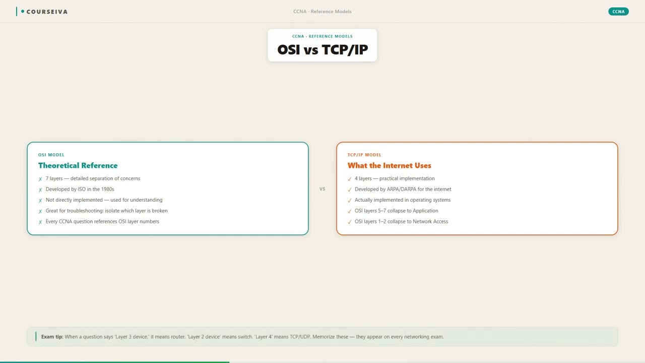
OSI Model
7 layers: Physical, Data Link, Network, Transport, Session, Presentation, Application
Developed by ISO in 1984
Conceptual framework, not implemented
Session and Presentation layers are separate
Used for teaching and troubleshooting
TCP/IP Model
4 layers: Network Interface, Internet, Transport, Application
Developed by DARPA in 1970s
Actual protocol suite used on the internet
Application layer combines Session, Presentation, and Application
Used for real-world communication
Watch Out for These
Mistake
The OSI model is the actual protocol stack used on the internet.
Correct
The internet uses the TCP/IP model (4 layers). The OSI model is a conceptual framework, not a protocol implementation.
Candidates often assume the OSI model is real because it's taught first.
Mistake
Layer 7 includes applications like web browsers or email clients.
Correct
Layer 7 (Application) provides network services to applications, but the application itself is not part of the layer. The layer includes protocols like HTTP, FTP, SMTP that applications use.
The name 'Application layer' is misleading.
Mistake
The Session layer handles encryption.
Correct
Encryption is a function of the Presentation layer (Layer 6). The Session layer manages dialogs and synchronization.
Both layers deal with managing communication, so functions are easily confused.
Mistake
A switch operates at Layer 3 because it can route traffic.
Correct
A standard switch operates at Layer 2 (Data Link). A multilayer switch can route at Layer 3, but the basic function of a switch is Layer 2 forwarding based on MAC addresses.
Modern switches often have routing capabilities, blurring the line.
Do You Actually Know This?
Reveal each answer, then mark whether you got it right. Score 60%+ to unlock the next chapter.
Frequently Asked Questions
Do I need to memorize the OSI layers in order for the CCNA exam?
Yes, absolutely. You must know the seven layers in order, both from top to bottom (Application to Physical) and bottom to top. Use mnemonics like 'Please Do Not Throw Sausage Pizza Away' (Physical to Application) or 'All People Seem To Need Data Processing' (Application to Physical). The exam will test your ability to identify which layer handles a specific function.
What is the difference between a segment and a packet?
A segment is the PDU at Layer 4 (Transport). For TCP, it's called a segment; for UDP, it's called a datagram. A packet is the PDU at Layer 3 (Network). The segment is encapsulated inside a packet. Many candidates confuse these terms. Remember: TCP segments, IP packets.
Is the OSI model still relevant today?
Yes, especially for troubleshooting and documentation. While the TCP/IP model is used in practice, the OSI model provides a more granular framework that helps isolate issues. For example, if a user can't connect, you can check each layer sequentially. The CCNA exam heavily tests OSI concepts.
How does encapsulation work with the OSI model?
When data is sent, each layer adds its own header (and sometimes trailer) to the data from the layer above. For example, the Transport layer adds a TCP header to form a segment. The Network layer adds an IP header to form a packet. The Data Link layer adds a frame header and trailer. The Physical layer converts the frame into bits. The receiving device performs the reverse process (de-encapsulation).
What layer does a firewall operate at?
A firewall can operate at multiple layers. Packet-filtering firewalls operate at Layer 3 and Layer 4 (based on IP addresses and ports). Stateful firewalls operate up to Layer 4. Application-layer firewalls (like proxies) operate at Layer 7. The CCNA exam expects you to know that basic ACLs work at Layers 3 and 4.
Why is the OSI model divided into seven layers?
The seven layers were chosen to separate distinct functions: physical transmission, data framing, routing, reliable delivery, session management, data representation, and application services. This modularity allows changes in one layer (e.g., replacing Ethernet with Wi-Fi) without affecting others. It also standardizes communication between different vendors.
What is the PDU at the Data Link layer?
The PDU at the Data Link layer is called a frame. A frame includes a header (with MAC addresses), the payload (the packet from Layer 3), and a trailer (with error detection information like FCS). For Ethernet, the maximum frame size is 1518 bytes.
Terms Worth Knowing
Ready to put this to the test?
You've just covered The OSI Model — now see how well it sticks with free CCNA 200-301 practice questions. Full explanations included, no account needed.
Done with this chapter?