What Is OSI model in Networking?
This page mentions older exam versions. See the Current Exam Context and Legacy Exam Context sections below for the updated mapping.
On This Page
What do you want to do?
Quick Definition
The OSI model is a way to think about how data travels from one computer to another over a network. It breaks down the process into seven layers, each with a specific job, like moving electrical signals or managing email. Think of it like a postal service that handles letters from sorting to delivery. It helps engineers design and troubleshoot networks more easily by focusing on one layer at a time.
Common Commands & Configuration
ping -c 4 8.8.8.8Sends four ICMP echo requests to the IP address 8.8.8.8 to test Layer 3 (Network layer) connectivity. Successful replies indicate that IP routing and the network layer is working between the source and destination.
Ping tests Network layer (Layer 3) and optionally verifies that IP addressing and routing are correct. Examiners often use ping to verify if the problem is at Layer 3 or below.
traceroute 8.8.8.8Traces the route packets take to reach the destination 8.8.8.8. It reveals each hop (router) along the path, showing delays and identifying where a failure might occur at Layer 3.
Traceroute is a Layer 3 troubleshooting command that shows the path through multiple routers. Exam questions may ask about which protocol it uses (ICMP or UDP) and what it tells you about network layer connectivity.
ipconfig /allDisplays full TCP/IP configuration for all network adapters on Windows, including IP address, subnet mask, default gateway, MAC address (Layer 2), and DNS servers.
This command provides information about both Layer 2 (MAC address) and Layer 3 (IP address) settings. Exams test your ability to identify incorrect subnet masks or default gateways as a Layer 3 problem.
arp -aDisplays the ARP (Address Resolution Protocol) cache, which maps IP addresses (Layer 3) to MAC addresses (Layer 2). Useful for troubleshooting Layer 2 to Layer 3 translation issues.
ARP operates between Layer 2 and Layer 3. Exam questions may ask: 'If a device cannot communicate with another on the same subnet, which command checks the MAC-to-IP mapping?' Answer: arp -a.
netstat -anLists all active network connections and listening ports (Layer 4). Shows state (e.g., LISTENING, ESTABLISHED), local and foreign addresses, and protocol (TCP/UDP).
This command is used to verify Transport layer (Layer 4) services. A common exam scenario: 'A user reports that a service is not working. Use netstat -an to see if the port is listening.'
nslookup example.comQueries the DNS server to resolve the domain name 'example.com' to an IP address (Layer 7/Application layer function). Also shows authoritative name servers.
DNS resolution is an Application layer function (though it relies on lower layers). Exam questions may test that DNS failures (e.g., 'server not found') are Layer 7 issues, not Layer 3.
tshark -i eth0 -Y 'http.request.method == GET'Uses the command-line packet analyzer tshark to capture HTTP GET requests on interface eth0, filtering for HTTP traffic (Layer 7). Useful for deep packet inspection at the Application layer.
Packet analyzers like wireshark or tshark operate at multiple layers. This command specifically captures Layer 7 requests. Exams may ask which tool can view HTTP headers.
OSI model appears directly in 43exam-style practice questions in Courseiva's question bank — one of the most-tested concepts on CompTIA Network+. Practise them →
Must Know for Exams
The OSI model is a core topic in virtually every major IT certification exam, especially at the entry and intermediate levels. For CompTIA Network+ (N10-008), the OSI model appears in objective 1.1, which requires candidates to explain the purpose and functions of each layer. Questions may ask you to identify which layer a specific protocol belongs to, such as 'At which OSI layer does TCP operate?' (Transport) or 'At which layer do routers function?' (Network). The exam also tests the encapsulation process and the PDU (Protocol Data Unit) names at each layer. Expect scenario-based questions where you must determine the most likely layer of a problem, for example, if a cable is unplugged, the issue is at the Physical Layer.
In the Cisco CCNA (200-301) exam, the OSI model is implicitly foundational. While the exam focuses on the TCP/IP model, many questions assume knowledge of the OSI layers. For instance, understanding the Data Link Layer is critical for configuring VLANs and STP, and the Network Layer is central to routing. The exam may ask about the differences between switches (Layer 2) and routers (Layer 3), or about the role of Layer 4 in port numbers.
For CompTIA Security+ (SY0-601), the OSI model is used to categorize threats and security controls. Questions might ask, 'At which OSI layer would you implement a firewall?' (Network Layer for packet filtering, or Application Layer for a web application firewall) or 'Which layer is responsible for encryption?' (Presentation Layer). The exam also uses the model to explain network attacks, like ARP poisoning at Layer 2.
Other exams like the AWS Certified Solutions Architect or Microsoft Azure fundamentals also touch on the OSI model indirectly, particularly when discussing load balancers (Layer 4 vs Layer 7) and network security groups. Even if the OSI model is not explicitly listed in the objectives, it provides the language to describe how cloud networking components interact.
Question types vary. Multiple-choice questions often ask you to match a layer to its description. Performance-based questions might ask you to order the layers in a simulation or identify the layer where a specific protocol operates. Troubleshooting scenarios are common: 'A user reports slow network performance. After checking cables and IP configuration, you suspect a duplex mismatch. At which OSI layer is this issue?' (Data Link Layer). To succeed, memorize the seven layers in order, know the PDU names (segment, packet, frame, bits), and associate key protocols and devices with their layers. Use mnemonics like 'Please Do Not Throw Sausage Pizza Away' for the top-to-bottom order (Physical, Data Link, Network, Transport, Session, Presentation, Application).
Simple Meaning
Imagine you want to send a letter to a friend in another city. You write the message, put it in an envelope, write the address, and drop it in a mailbox. From there, the postal service takes over: your local post office sorts it, trucks move it between cities, and another post office delivers it to your friend's mailbox. In networking, data travels in a similar way, and the OSI model is a blueprint that describes each step of that journey.
The OSI model stands for Open Systems Interconnection model. It was created in the 1980s by the International Organization for Standardization (ISO) to help different computer systems communicate with each other. Before the OSI model, every company had its own proprietary way of networking, which made it hard for devices from different manufacturers to work together. The model fixed this by providing a common language for network communication.
The model has seven layers, numbered from 7 to 1. Layer 7 is the top layer, closest to the user, and Layer 1 is the bottom layer, closest to the physical hardware. Each layer has a specific job and only talks to the layers directly above and below it. This modular design means that if a problem occurs in one layer, engineers can fix it without changing the others.
To make this more concrete, think of ordering a pizza over the phone. The Application Layer (Layer 7) is you deciding what pizza to order and picking up the phone. The Presentation Layer (Layer 6) translates your thoughts into a language the phone system understands. The Session Layer (Layer 5) starts and ends the call. The Transport Layer (Layer 4) ensures your order is complete and correct. The Network Layer (Layer 3) figures out the best route for your voice to travel. The Data Link Layer (Layer 2) packages your voice into smaller chunks that can be sent over wires. And the Physical Layer (Layer 1) is the phone line itself carrying electrical or light signals.
In real-world IT, the OSI model is a mental tool, not a set of rules that every device follows exactly. Modern networks mostly use the TCP/IP model, which has fewer layers, but the OSI model is still taught because it gives a more detailed and educational view of how networking works. It helps technicians diagnose problems: for example, if you can't connect to the internet, you might start at Layer 1 (check cables) and work your way up to Layer 3 (check IP addresses) and Layer 7 (check if a website is down). Without the OSI model, troubleshooting would be like trying to find a leak in a pipe without knowing which section to inspect.
For learners, the OSI model is foundational. It appears in almost every IT certification exam, from CompTIA Network+ to Cisco CCNA. Understanding the layers and their functions helps you grasp how protocols like TCP, IP, and HTTP work together. It also clarifies why certain devices belong at certain layers, like switches at Layer 2 and routers at Layer 3. Once you internalize the OSI model, you have a map of the entire networking landscape.
Full Technical Definition
The Open Systems Interconnection (OSI) model is a conceptual framework developed by ISO/IEC 7498-1 that standardizes the functions of a computing or telecommunication system into seven abstraction layers. Each layer serves a specific role in the process of data transmission, from the physical transmission of bits to the application interface presented to end users. The model is strictly hierarchical, meaning that data flows from one layer to the next, and each layer communicates only with its immediate neighbor layers (above and below). This design promotes interoperability between different vendors' hardware and software.
Layer 7: Application Layer This layer provides network services directly to end-user applications. It defines protocols for resource sharing, remote file access, directory services, and email. Common protocols include HTTP, FTP, SMTP, DNS, and Telnet. The Application Layer does not include the user applications themselves, but rather the protocols that those applications use to communicate over the network. For example, a web browser uses HTTP at this layer.
Layer 6: Presentation Layer This layer is responsible for data translation, encryption, and compression. It ensures that data from the Application Layer is transformed into a format that the lower layers can transmit. For example, it converts character encodings (ASCII to EBCDIC) and handles data compression (like JPEG for images) and encryption (like SSL/TLS). The Presentation Layer acts as a data translator so that two systems with different internal representations can exchange information.
Layer 5: Session Layer This layer establishes, manages, and terminates sessions between applications on different hosts. A session includes the setup, maintenance, and teardown of a communication link. It provides synchronization points in the data stream to allow recovery from failures. For example, if a large file transfer fails halfway through, the session layer can resume from the last checkpoint. Common protocols include NetBIOS, RPC, and PPTP.
Layer 4: Transport Layer This layer provides reliable or unreliable delivery of data between end systems. It segments data from the upper layers, reassembles segments on the receiving end, and provides error checking and flow control. The two primary protocols at this layer are TCP (Transmission Control Protocol), which offers connection-oriented, reliable delivery with retransmission, and UDP (User Datagram Protocol), which offers connectionless, unreliable delivery suitable for streaming media. This layer is also responsible for multiplexing different application streams using port numbers.
Layer 3: Network Layer This layer handles logical addressing and routing. It determines the best path for data to travel from source to destination across multiple networks. It uses IP addresses and routers to forward packets. Key protocols include IP (IPv4 and IPv6), ICMP (for error reporting and diagnostics), and routing protocols like OSPF, BGP, and RIP. The Network Layer fragments packets when necessary to meet the maximum transmission unit (MTU) of the underlying link.
Layer 2: Data Link Layer This layer provides node-to-node data transfer across the physical link. It packages data into frames, adds the source and destination MAC addresses (hardware addresses), and handles error detection and correction using techniques like cyclic redundancy check (CRC). The Data Link Layer is divided into two sublayers: the Logical Link Control (LLC) sublayer, which interfaces with the Network Layer, and the Media Access Control (MAC) sublayer, which controls access to the physical medium. Ethernet, Wi-Fi (802.11), and PPP operate at this layer. Switches are primarily Layer 2 devices.
Layer 1: Physical Layer This layer defines the physical characteristics of the network, such as voltage levels, timing, data rates, cable types, connectors, and signal modulation. It transmits raw bits (0s and 1s) over a transmission medium, like copper wires, fiber optics, or radio waves. Hubs, repeaters, and modems operate at this layer. Specifications like RS-232, 1000BASE-T, and USB fall under Layer 1.
Data encapsulation and de-encapsulation are key processes in the OSI model. When data travels from the Application Layer down to the Physical Layer, each layer adds its own header (and sometimes a trailer) to the data. This is called encapsulation. The resulting unit at each layer has a specific name: at Layer 4 it is a segment (TCP) or datagram (UDP), at Layer 3 it is a packet, at Layer 2 it is a frame, and at Layer 1 it is bits. On the receiving side, the process reverses: each layer strips its corresponding header and passes the payload up to the next layer.
The OSI model is not used as a strict protocol stack in modern networks; instead, the TCP/IP model (or Internet protocol suite) is the de facto standard. However, the OSI model remains invaluable for education, documentation, and troubleshooting. For example, a network technician troubleshooting a connectivity issue might use the 'bottom-up' approach: check Physical Layer (cable connections), then Data Link Layer (MAC address table), then Network Layer (IP configuration), and so on. The model also provides a clear taxonomy for security professionals to map threats to specific layers and for developers to understand where their application protocols fit in the network stack.
the OSI model is a seven-layer abstraction that describes how data moves from a user application on one device to a user application on another device across a network. It provides a universal language for describing network functions and a blueprint for interoperability.
Real-Life Example
Think of ordering a pizza over the phone. This everyday activity has many parallels to the OSI model layers. Let's map it out.
You (the user) decide you want a pepperoni pizza with extra cheese. This is the data you want to send. At the Application Layer (Layer 7), you pick up your phone and dial the pizza place. The phone app itself is not part of the model, but the protocols that let you make the call (like SIP for Voice over IP) are. You tell the person on the other end your order. In networking, this is where your email client talks to an SMTP server or your browser sends an HTTP request.
Now, the pizza place wants to make sure the order is clear: they write it down in a standard format, maybe enter it into a computer system. This is the Presentation Layer (Layer 6). They might also decide to encode the order in a specific way to avoid confusion (like spelling the name 'Johnson' using a phonetic alphabet). This layer translates your request into a machine-friendly format and can encrypt or compress it.
Next, the person taking the order says, 'Thank you, your order will be ready in 20 minutes,' and hangs up. Starting and ending the call is the Session Layer (Layer 5). It coordinates the conversation: it initiates, maintains, and terminates the connection. If the line drops halfway, the session layer ensures you call back and resume from where you left off.
Your order goes into the kitchen. The chef reads the ticket and decides to cook the pizza. This is the Transport Layer (Layer 4). It's responsible for making sure the whole order is received correctly. If it's a complex order (like multiple pizzas), the chef segments it into individual pizzas. If one pizza burns, the chef remakes it (retransmission). The kitchen also manages how many orders come in at once, so the chef doesn't get overwhelmed (flow control).
Now the delivery driver looks at a map and decides the best route to your house. This is the Network Layer (Layer 3). The driver uses your street address (IP address) to pick the path. If the usual street is closed, the driver reroutes using a GPS (routing protocol). This layer is all about getting the data from one network to another, jumping through routers.
The driver gets in the car and begins driving. But before leaving, they put the pizza into a special insulated bag (encapsulation). That bag is like a frame at the Data Link Layer (Layer 2). The bag has a label with your house number and street (MAC address) for the last leg of the journey. The driver follows the street signs and delivers to the correct house. This layer handles the hop between two directly connected devices, like a computer to a switch.
Finally, the driver walks to your front door and hands you the pizza. This is the Physical Layer (Layer 1). It's the car itself, the road, the tires moving, the electrical signals in the car's engine. In networking, it's the copper wire, the fiber optic cable, the radio waves for Wi-Fi. Without this layer, nothing else can happen.
If the pizza arrives cold or wrong, you can troubleshoot. If the pizza is missing (lost data), you might blame the kitchen (Transport Layer) or the driver (Network Layer). If the pizza arrives but the box is smashed (corrupted data), you look at the bag (Data Link Layer) or the car (Physical Layer). This analogy shows how the OSI model helps isolate problems and understand the flow of data.
Why This Term Matters
The OSI model matters because it provides a universal framework for understanding and designing network systems. In real IT practice, networks are complex and involve many different vendors, protocols, and hardware. Without a common reference model, diagnosing a network issue would be like trying to fix a car engine without a diagram. The OSI model gives engineers a structured way to isolate problems: if a user cannot access a website, the technician can start by checking the physical cable (Layer 1), then the network configuration (Layer 3), and finally the application settings (Layer 7). This saves time and prevents guesswork.
the OSI model is crucial for interoperability. When a network engineer configures a router from Cisco and a switch from Juniper, the OSI model ensures that both devices understand the same concepts at Layer 2 and Layer 3. It also helps when integrating new technologies. For example, when a company moves from IPv4 to IPv6, the change primarily happens at Layer 3 (Network Layer). The OSI model clarifies that this change should not affect the Physical Layer or the Application Layer, so other parts of the network can remain the same.
For security professionals, the OSI model is a lens for understanding attacks. A physical theft of a cable is a Layer 1 attack, a MAC address spoofing attack is Layer 2, a routing table poisoning is Layer 3, a SYN flood is Layer 4, and a SQL injection is Layer 7. Knowing which layer an attack targets helps in choosing the right defense, such as encryption at Layer 6 or firewalls at Layer 3 and 4.
the OSI model is not just an academic concept. It is a practical tool that underpins how IT professionals think about, design, and maintain networks. Mastering it is essential for any serious IT career.
How It Appears in Exam Questions
The OSI model appears in exam questions in a few distinct patterns. The most common is direct identification: 'At which layer of the OSI model do routers operate?' or 'Which layer provides reliable end-to-end delivery of data?' These test your ability to recall the layer functions and associated devices. Expect reverse questions like 'This layer is responsible for converting data formats and encrypting messages, which layer is it?' (Presentation Layer).
Scenario-based questions are frequent in CompTIA Network+ and CCNA. For example: 'A network technician replaces a faulty switch, but users still cannot communicate. The technician verifies that the cables are connected and the IP addresses are correct. At which layers have the issues been eliminated?' The answer would be Physical Layer (cables) and Network Layer (IP addresses), leaving layers 2, 4, 5, 6, and 7 as potential problem areas. Another common scenario: 'A user in the finance department cannot access the web server. Other departments can access it. The technician pings the server and it responds. At which OSI layers have problems been ruled out?' A successful ping rules out Layers 1-3, so the issue is likely at Layers 4-7.
Encapsulation questions are also common. You might be asked: 'When an HTTP request is sent, which order of encapsulation occurs as the data moves down the OSI stack?' The correct order is: data, segment, packet, frame, bits. Some questions ask about the Protocol Data Unit (PDU) name at each layer: 'What is the PDU at the Transport Layer?' (Segment for TCP, Datagram for UDP).
Troubleshooting questions can be more involved. For example: 'A user reports that they can access websites by IP address but not by domain name. Which OSI layer is the most likely source of the problem?' The answer is the Application Layer (Layer 7) because DNS resolution fails. Another: 'A company has intermittent network outages. The IT team discovers high collision rates on the network. Which layer of the OSI model does this affect?' (Layer 2, Data Link, collisions are a CSMA/CD issue).
Performance-based questions in CCNA may require you to identify the layer at which a particular protocol operates by dragging protocols into a layer diagram. For instance, you might drag HTTP to Layer 7, TCP to Layer 4, IP to Layer 3, Ethernet to Layer 2, and Cat5e to Layer 1.
exam questions test two things: your rote memory of the layers and their characteristics, and your ability to apply that knowledge to real-world troubleshooting scenarios. Practice explaining problems in terms of layers to build this skill.
Practise OSI model Questions
Test your understanding with exam-style practice questions.
Example Scenario
Scenario: A small company has ten employees who all use a shared network drive to store files. One morning, a user named Maria reports that she cannot access the network drive. She gets an error saying 'Network path not found.' Her computer still shows that she can browse the internet, and her email works fine. The network administrator, Tom, needs to find the problem.
Tom starts by thinking about the OSI model. Since Maria can access the internet and email, he knows that the Physical Layer (Layer 1) is likely fine, the cable is plugged in, and the Wi-Fi is connected. The Data Link Layer (Layer 2) is probably working because she can communicate with the router to get internet access. The Network Layer (Layer 3) seems okay because she can reach servers on the internet by IP address (DNS is working). So the issue is probably higher up.
Tom then considers the Transport Layer (Layer 4). The network drive uses specific ports, like 445 for SMB (Server Message Block). He wonders if a firewall is blocking that port. He also checks if the network drive server (a Windows file server) is running. He tries to ping the server's IP address from Maria's computer, the ping is successful, which means Layers 1-3 are working. He then tries to access the server by its name: \\fileserver\. It fails.
Tom now suspects the Session Layer (Layer 5) or the Application Layer (Layer 7). He checks Maria's credentials and finds that her account has been locked out. He resets the password. Now Maria can access the network drive. The problem was at the Application Layer (Layer 7) because the authentication service that allows access to the shared files was unavailable to Maria's account. By using the OSI model, Tom isolated the issue to the upper layers and solved it quickly.
If Tom had not used a structured approach, he might have wasted time checking cables or reinstalling network drivers. The scenario shows how the OSI model guides a logical, step-by-step diagnosis.
Common Mistakes
Confusing the order of the layers, especially swapping the Session and Presentation layers.
The OSI layers must be in a specific order from layer 7 (Application) to layer 1 (Physical). The Presentation Layer is layer 6, directly below Application. The Session Layer is layer 5, below Presentation. Getting the order wrong leads to incorrect answers on exam questions about encapsulation or layer functions.
Memorize the mnemonic 'All People Seem To Need Data Processing' (Application, Presentation, Session, Transport, Network, Data Link, Physical) from top to bottom.
Thinking that switches operate at Layer 3 (Network) instead of Layer 2 (Data Link).
Switches forward frames based on MAC addresses, which are Layer 2 addresses. Routers forward packets based on IP addresses (Layer 3). A common misconception is that all 'smart' devices are at Layer 3, but switches are primarily Layer 2 devices, although multilayer switches can perform Layer 3 routing.
Remember: switches use MAC addresses (Layer 2), routers use IP addresses (Layer 3).
Believing that the OSI model is the exact protocol stack used in the Internet.
The Internet uses the TCP/IP model, which has four layers (Application, Transport, Internet, Network Access). The OSI model is a conceptual framework, not a strict implementation. While many textbooks map TCP/IP to OSI layers, they are not identical. For example, the OSI model's Session and Presentation layers are often absorbed into TCP/IP's Application Layer.
Know that the OSI model is for learning and troubleshooting. Real-world networking follows the TCP/IP model. Know both and how they relate.
Assuming that all protocols fit neatly into a single layer.
Some protocols, like ARP, operate at the boundary of Layer 2 and Layer 3. Others, like DNS, use the Application Layer but rely on Transport Layer services. The OSI model is not always a perfect fit, but exams usually expect you to assign protocols to a primary layer.
For exam purposes, assign each protocol to its most commonly associated layer: HTTP, FTP, DNS at Layer 7; TCP, UDP at Layer 4; IP at Layer 3; Ethernet at Layer 2; Cat5e at Layer 1.
Confusing the function of the Transport Layer with the Network Layer.
The Transport Layer (Layer 4) provides end-to-end communication, reliability, and port multiplexing. The Network Layer (Layer 3) provides logical addressing and routing between different networks. Learners sometimes think routing happens at Layer 4 or that port numbers are used at Layer 3.
Layer 3 is about getting packets from source to destination across networks (routing). Layer 4 is about the quality of that delivery (reliable vs. unreliable) and which application gets the data (ports).
Forgetting that the Physical Layer transmits bits, not frames or packets.
The Physical Layer deals with raw binary bits in the form of electrical signals, light pulses, or radio waves. Frames and packets are handled by higher layers. Mixing these up can cause confusion in questions about PDU names.
Layer 1 PDU: bits. Layer 2 PDU: frame. Layer 3 PDU: packet. Layer 4 PDU: segment (TCP) or datagram (UDP).
Thinking that encryption and decryption occur at the Transport Layer.
Encryption is primarily a function of the Presentation Layer (Layer 6) or, in practice, often implemented at the Application Layer (e.g., TLS in HTTPS). The Transport Layer can be encrypted (e.g., TLS over TCP), but the encryption itself is not a Transport Layer function.
Encryption and compression are Layer 6 (Presentation) responsibilities. The Transport Layer is concerned with reliable delivery and flow control.
Exam Trap — Don't Get Fooled
{"trap":"In an exam question, you are asked: 'A user can ping the IP address of a server but cannot access the web page hosted on that server. At which OSI layer is the issue?'","why_learners_choose_it":"Many learners read the word 'ping' and immediately think of the Network Layer (Layer 3).
They choose Layer 3 because ping uses ICMP, which is often associated with Layer 3. They may also think that if the ping works, everything below Layer 4 is fine, but they forget that a web page requires a different protocol (HTTP) and a different port (TCP 80 or 443).","how_to_avoid_it":"Remember: ping uses ICMP, which operates at Layer 3.
A successful ping confirms that Layers 1 through 3 are functioning correctly. However, a web page requires the Application Layer (HTTP) and the Transport Layer (TCP). If the ping works but the web page does not, the issue is likely at Layer 4 (if a firewall blocks port 80) or Layer 7 (if the web server is misconfigured).
Always consider the specific protocol and port needed for the failed service."
Commonly Confused With
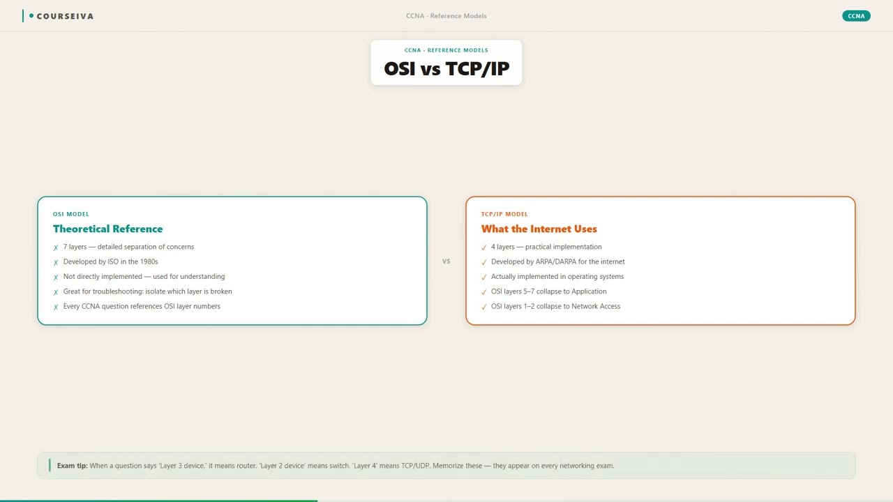
The TCP/IP model is a more concise, four-layer framework that is actually used on the Internet. The OSI model has seven layers and is a theoretical reference. The TCP/IP model combines the Application, Presentation, and Session layers into a single Application Layer, and it combines the Data Link and Physical layers into a single Network Access Layer.
When you send an email, the TCP/IP model says the email protocol (SMTP) is in the Application Layer, while the OSI model splits that into Application (SMTP), Presentation (data formatting), and Session (session management).
The DoD (Department of Defense) model is another name for the TCP/IP model, used mainly in military contexts. It has four layers: Process/Application, Host-to-Host, Internet, and Network Access. It is equivalent to the TCP/IP model, not the OSI model.
In the DoD model, the Internet layer is equivalent to the OSI Model's Network Layer (Layer 3).
Encapsulation is the process of adding headers (and sometimes trailers) as data moves down the OSI stack. It is not a layer or a model, but a function that occurs within the model. Learners sometimes confuse the term 'encapsulation' with 'encryption', but encapsulation is about wrapping data, not scrambling it.
When you send a web request, the HTTP data is encapsulated into a TCP segment (Layer 4), then into an IP packet (Layer 3), then into an Ethernet frame (Layer 2), and finally into bits on the wire (Layer 1).
A protocol stack is a set of network protocols that work together, like TCP/IP. The OSI model is a reference model that describes how protocols should be organized. A protocol stack implements a model, but the OSI model is not itself a protocol stack.
In a Cisco CCNA lab, you configure a 'protocol stack' consisting of Ethernet (Layer 2), IP (Layer 3), and TCP (Layer 4). This stack follows the OSI model's structure.
The TCP/IP model has only four layers, which sometimes are mapped to OSI layers. The mapping is not one-to-one. For example, TCP/IP's Application Layer combines OSI Layers 5, 6, and 7. Learners often try to match each OSI layer to a single TCP/IP layer, but that is incorrect.
An HTTP request: In OSI, it goes through Layer 7 (HTTP), Layer 6 (maybe MIME encoding), Layer 5 (session management). In TCP/IP, all those functions are considered part of the Application Layer.
Step-by-Step Breakdown
Application Layer (Layer 7) Initiates Communication
A user application, such as a web browser or email client, creates data that needs to be sent over the network. The Application Layer defines the protocols (like HTTP, FTP, SMTP) that the application uses to format the data for network transmission. This layer does not include the application itself but provides the interface between the application and the network.
Presentation Layer (Layer 6) Translates Data Formats
The data from the Application Layer is translated into a standard format that can be understood by the receiving system. This layer handles character encoding conversion (e.g., ASCII to EBCDIC), data compression to reduce size, and encryption/decryption for security. It ensures that the data appears the same to the receiving application regardless of the underlying system architecture.
Session Layer (Layer 5) Manages Dialog Control
This layer establishes, maintains, and terminates the connection between two communicating applications. It manages the session by setting up checkpoints, synchronizing data streams, and handling recovery if the connection drops. For example, in a video conference, the Session Layer keeps track of who is speaking and ensures the audio and video streams are synchronized.
Transport Layer (Layer 4) Segments Data and Ensures Reliability
The Transport Layer takes the data from the Session Layer and breaks it into smaller segments (for TCP) or datagrams (for UDP). It adds headers containing source and destination port numbers to identify which application should receive the data. This layer provides error detection, flow control, and, in the case of TCP, retransmission of lost segments to ensure reliable delivery.
Network Layer (Layer 3) Adds Logical Addressing and Routes Packets
The Network Layer encapsulates the segments from Layer 4 into packets by adding a header that includes the source and destination IP addresses. It determines the optimal path for the packet to travel from the source network to the destination network using routing protocols. Routers operate at this layer and make forwarding decisions based on the IP address.
Data Link Layer (Layer 2) Adds Physical Addressing and Frames Data
The Data Link Layer takes the packet from the Network Layer and encapsulates it into a frame by adding a header with source and destination MAC addresses. This layer also adds a trailer with a Frame Check Sequence (FCS) for error detection. It is responsible for node-to-node communication across a single link. Switches and bridges operate here. It also controls media access (CSMA/CD for Ethernet).
Physical Layer (Layer 1) Transmits Bits Over the Medium
The frame from the Data Link Layer is converted into a stream of bits (0s and 1s) by this layer. The Physical Layer defines the electrical, mechanical, and procedural characteristics of the transmission medium. It sends the signals over cables (copper, fiber) or through wireless waves. Hubs, repeaters, and cables operate at this layer.
Signal Travels to the Destination and Is De-encapsulated
On the receiving end, the Physical Layer receives the bits and passes them up to the Data Link Layer. The Data Link Layer checks the FCS for errors, strips its header, and passes the packet to the Network Layer. Each layer removes its respective header, reversing the encapsulation process until the original data reaches the Application Layer on the receiving device. This step-by-step process ensures that the data is correctly delivered to the intended application.
The Seven Layers of the OSI Model: A Comprehensive Breakdown
The Open Systems Interconnection (OSI) model is a conceptual framework used to understand and standardize network communication. It divides the complex process of data transmission into seven distinct layers, each with a specific function. From the physical transmission of bits to the application interfaces that users interact with, the OSI model provides a universal language for networking professionals. For IT certification exams, mastering the OSI model is not optional; it is foundational. Every layer has its own protocols, data units, and responsibilities, and exam questions frequently test your ability to identify which layer handles a given task or to recall the order of the layers from top to bottom or bottom to top.
The seven layers, from Layer 7 down to Layer 1, are: Application, Presentation, Session, Transport, Network, Data Link, and Physical. A common mnemonic to remember the top-down order is 'All People Seem To Need Data Processing.' The Application layer (Layer 7) is closest to the end user and provides network services to applications, such as email clients (SMTP), web browsers (HTTP), and file transfer (FTP). The Presentation layer (Layer 6) handles data formatting, encryption, and compression, ensuring that data from the Application layer is in a readable format for the receiving system. The Session layer (Layer 5) manages dialogs between devices, establishing, maintaining, and synchronizing interactions. The Transport layer (Layer 4) ensures reliable or unreliable delivery of data segments using protocols like TCP (connection-oriented, reliable) and UDP (connectionless, best-effort). The Network layer (Layer 3) handles logical addressing (IP addresses) and routing packets across different networks. The Data Link layer (Layer 2) deals with physical addressing (MAC addresses) and frames, managing access to the physical medium and error detection via framing. Finally, the Physical layer (Layer 1) transmits raw bits over a physical medium such as copper wires, fiber optics, or radio waves. Understanding the encapsulation process, where each layer adds its own header (and sometimes trailer) to the data as it travels down the stack, is critical. For example, a web request begins at Layer 7 as data, gets wrapped in a Layer 4 segment header (TCP), then a Layer 3 packet header (IP), and finally a Layer 2 frame header (Ethernet) before being sent as bits at Layer 1. Exams love to ask about this encapsulation process and the names of protocol data units (PDUs) at each layer: data (Layer 5-7), segment (Layer 4), packet (Layer 3), frame (Layer 2), and bits (Layer 1).
OSI Model vs. TCP/IP Model: Key Differences and Exam Comparisons
While the OSI model is a theoretical reference model, the TCP/IP model is the practical suite used on the modern internet. IT certification exams, including CompTIA Network+ and Cisco CCNA, frequently test the differences between these two models. The OSI model has seven layers, whereas the TCP/IP model has four: Application, Transport, Internet, and Network Access.
Understanding how these two models map to each other is a common exam topic. In the TCP/IP model, the Application layer roughly corresponds to the OSI's Application, Presentation, and Session layers combined. The Transport layer in both models serves the same purpose (TCP or UDP).
The TCP/IP Internet layer maps directly to the OSI Network layer. The TCP/IP Network Access layer encompasses the OSI Data Link and Physical layers. One key conceptual difference is that the OSI model was developed first as a strict standard by the International Organization for Standardization (ISO), while TCP/IP was developed later by the Department of Defense (DoD) and became the de facto standard due to its implementation in Unix and the internet.
The OSI model is often praised for its modularity and clear separation of concerns, making it excellent for teaching and troubleshooting. For example, if a network engineer suspects an encryption issue, they know to look at the Presentation layer (Layer 6) in the OSI model, which is not explicitly defined in TCP/IP. In TCP/IP, encryption is considered a function of the application.
Exam questions may ask you to identify which OSI layer corresponds to a specific TCP/IP layer or to recall the layers of each model in order. Another point of difference is that the OSI model explicitly separates the Session layer, which manages dialogs, whereas TCP/IP lumps this into the Application layer. The OSI model defines a distinct Presentation layer for data translation, whereas TCP/IP does not.
When troubleshooting, using the OSI model as a diagnostic framework is common practice. For instance, if you can ping a device (Layer 3 works) but cannot browse a website (Layer 7 fails), the issue likely lies at Layer 7. This layered approach is a cornerstone of networking exams and is often presented in scenario-based questions where you must pinpoint the layer causing the problem.
Encapsulation and De-encapsulation in the OSI Model: The Data Journey
Encapsulation is the process by which data is prepared for transmission over a network, and de-encapsulation is the reverse process on the receiving end. This concept is central to the OSI model and is tested heavily in certification exams. When data moves from an application down through the OSI layers on the sending device, each layer adds its own header (and sometimes a trailer) to the data unit it receives from the layer above.
The resulting structure is called a Protocol Data Unit (PDU). At the Application, Presentation, and Session layers (Layers 5-7), the PDU is generically called 'data.' At the Transport layer (Layer 4), the PDU becomes a 'segment' if using TCP or a 'datagram' if using UDP.
The Transport layer header includes source and destination port numbers, sequence numbers (for TCP), and checksums. At the Network layer (Layer 3), the PDU is called a 'packet.' The Network layer header includes logical addresses (source and destination IP addresses) and routing information.
At the Data Link layer (Layer 2), the PDU is called a 'frame.' The frame header includes physical addresses (source and destination MAC addresses) and the frame trailer usually contains a Frame Check Sequence (FCS) for error detection. Finally, at the Physical layer (Layer 1), the PDU is simply 'bits' - the actual 1s and 0s transmitted over the physical medium.
On the receiving end, the process is reversed: de-encapsulation. The Physical layer receives the bits and passes them up to the Data Link layer, which checks the FCS, strips the frame header and trailer, and passes the packet up to the Network layer. The Network layer examines the IP header, determines the next hop or destination, and passes the segment up to the Transport layer.
The Transport layer uses the port numbers to determine which application should receive the data, reassembles segments if necessary, and passes the data up through the Session and Presentation layers to the Application layer. Exam questions often present a scenario where you must identify the PDU at a specific layer, or trace the header information that gets added or removed. For instance, a common question asks: 'At which layer does a MAC address get added to the data?'
The answer is Layer 2 (Data Link). Another typical question: 'What information is contained in the Transport layer header?' Answer: Port numbers. Understanding encapsulation also helps in troubleshooting.
If a packet is lost, using a tool like Wireshark to capture frames at Layer 2 allows you to see the IP and TCP headers, helping isolate the problem. This layered approach is why the OSI model remains relevant even in modern networking.
Using the OSI Model as a Step-by-Step Troubleshooting Framework
One of the most practical applications of the OSI model in IT is as a troubleshooting methodology. Instead of randomly checking cables or firewalls, networking professionals use the OSI model to isolate issues layer by layer. Certification exams, especially CompTIA Network+ and CCNA, often feature troubleshooting questions that require you to identify which OSI layer a problem belongs to, based on the symptoms.
The standard approach is to start at the Physical layer (Layer 1) and work up, or sometimes start at the Application layer (Layer 7) and work down, depending on the scenario. Starting from Layer 1 is often preferred because physical issues are common and easy to overlook. For example, a user cannot access the network.
The first step is to check if the network cable is plugged in properly, if the link lights are on, and if the device is receiving power (Layer 1). If those are fine, move to Layer 2: check for MAC address issues, collisions, or incorrect VLAN configurations. Then to Layer 3: verify IP addressing, subnet masks, default gateways, and routing tables.
Layer 4: check if firewalls are blocking specific ports, or if TCP handshakes are completing. Layers 5-7: check application settings, authentication, and encryption. A specific example: A user can ping (Layer 3 success) but cannot browse a website (Layer 7 failure).
This isolates the problem to Layers 5-7, perhaps an HTTP issue or a proxy configuration error. Another example: If a user can access local resources but not remote ones, the problem is likely at Layer 3 (routing) or Layer 2 (VLAN). Exam questions often present a scenario with specific symptoms and ask which layer you would check first.
For instance, 'A user receives a 'destination unreachable' error. Which layer is most likely involved?' The correct answer is Layer 3 (Network) because ICMP, which is used for ping and error messages, operates at Layer 3.
Another typical exam clue: 'If you can successfully run ipconfig and see an IP address, but you cannot ping the default gateway, what layer is the problem at?' The answer is Layer 3 (if the address is correct but routing fails) or Layer 2 (if the ARP resolution fails). The OSI model also helps in understanding the tools used at each layer.
For Layer 1, use a cable tester. For Layer 2, use a protocol analyzer like Wireshark to see frames. For Layer 3, use ping, traceroute, and ipconfig. For Layer 4, use netstat or telnet.
For Layers 5-7, use application-specific logs. By systematically applying the OSI model, you can diagnose network problems efficiently, which is exactly what certification exams want to validate.
Troubleshooting Clues
No link light on the network interface
Symptom: The network port on the device or switch has no LED illuminated. The device cannot communicate with any other device.
This is a Layer 1 (Physical) problem. The physical medium is not providing a valid signal. Possible causes: defective cable, wrong cable type (e.g., straight-through vs. crossover for switch-switch), damaged port, or device powered off.
Exam clue: Exam questions often describe a scenario where a user has no connectivity and the first troubleshooting step is to check the link light. This tests whether you recognize a Physical layer issue.
Incorrect subnet mask
Symptom: The device can communicate with some hosts on the network but not others, even though they appear to be on the same IP subnet.
This is a Layer 3 (Network) problem. The subnet mask determines which part of the IP address is the network portion. An incorrect mask causes the device to believe hosts are on different networks than they actually are, leading to misrouting. For example, using /24 instead of /16 on a class B network.
Exam clue: Common exam question: 'A host with IP 192.168.1.10 and subnet mask 255.255.0.0 can ping 192.168.2.1 but not 192.168.1.1. What is wrong?' Answer: The subnet mask is too broad (allowing local traffic to reach .2.x but not the gateway).
Duplicate IP address on the network
Symptom: The device intermittently loses connectivity, or an 'IP address conflict' error appears. One or both devices with the same IP fail to communicate reliably.
This is a Layer 3 (Network) addressing problem. Both devices claim the same logical address. The network’s ARP tables become inconsistent, and switches may forward traffic to the wrong device. The DHCP server or static configuration needs correction.
Exam clue: Exams may present a scenario where after adding a new device, an existing device shows connectivity issues with 'address already in use.' The solution is to change the IP of the new device or release/renew DHCP.
ARP table corruption or missing entry
Symptom: A device can ping its own IP (127.0.0.1) and the local switch's interface, but cannot ping another host on the same subnet.
This is a Layer 2/3 boundary issue. The Network layer (Layer 3) has the correct IP address, but the Data Link layer (Layer 2) cannot resolve the MAC address. The ARP cache might have a stale entry or the target host does not respond to ARP requests. Clearing the ARP cache often resolves it.
Exam clue: Exam trick: 'A user complains they cannot reach a neighbor's PC on the same subnet. Ping to 127.0.0.1 works. What command should you try first?' Answer: arp -d to flush the ARP cache.
Firewall blocking a specific port
Symptom: A web server responds to ping (Layer 3 works) but the browser shows 'connection refused' or 'timeout' when accessing the website.
This is a Layer 4 (Transport) or Layer 7 (Application) issue. The firewall is configured to block inbound or outbound traffic on TCP port 80 (HTTP) or 443 (HTTPS). The ICMP echo (ping) is not blocked, but the TCP handshake is not completing.
Exam clue: Exam questions often differentiate between ping success (Layer 3) and application failure (Layer 4 or 7). They might ask: 'Which layer would you check if FTP is blocked but ICMP works?' Answer: Layer 4 (firewall rules).
MTU mismatch
Symptom: Small packets (e.g., ping with size 100 bytes) work, but larger packets (e.g., ping with size 2000 bytes) fail or cause fragmentation errors. Or file downloads hang.
This is a Layer 3 (Network) issue related to the Maximum Transmission Unit. Different network links have different MTUs (e.g., Ethernet 1500 bytes, PPPoE 1492). If a router or device sends a packet larger than the next link's MTU without the DF (Don't Fragment) flag, it gets fragmented or dropped. A mismatch causes large packets to be silently dropped.
Exam clue: Exam asks: 'You can ping with 100 bytes but not with 1500 bytes. What is the likely issue?' Answer: MTU mismatch. Path MTU Discovery or manual MTU setting is needed.
Default gateway misconfiguration
Symptom: The device can communicate with other hosts on the local subnet (same VLAN) but cannot access the internet or other subnets.
This is a Layer 3 problem. The device's default gateway IP is either missing, incorrect, or unreachable. Without a valid gateway, the device cannot send packets outside its own subnet. The router's interface serving as the gateway must also be in the same subnet as the device.
Exam clue: Classic exam question: 'A PC gets an IP address from DHCP but cannot browse external websites. However, it can ping the DHCP server. What is most likely wrong?' Answer: Default gateway not set or wrong.
Wireless interference or signal loss
Symptom: The wireless client shows a good signal but experiences frequent disconnects, slow speeds, or packet loss. Wired connections work fine.
This is a Layer 1 (Physical) problem for wireless networks. Electromagnetic interference from other devices (microwaves, cordless phones), physical obstacles (walls, metal), or channel congestion from nearby access points degrades the wireless signal. Although the connection establishes, the bit error rate increases, causing retransmissions at higher layers.
Exam clue: Exam scenario: 'Users on the 2.4 GHz band experience intermittent drops when the microwave is on. Which layer should you investigate?' Answer: Layer 1 (Physical) – interference.
Learn This Topic Fully
This glossary page explains what OSI model means. For a complete lesson with labs and practice, see the topic guide.
Covered in These Exams
Current Exam Context
Current exam versions that test this topic — use these objectives when studying.
CISSPCISSP →N10-009CompTIA Network+ →200-301Cisco CCNA →220-1201CompTIA A+ Core 1 →SC-900SC-900 →PCAGoogle PCA →Legacy Exam Context
Older materials may mention these exam versions, but learners should use the current objectives for their target exam.
N10-008N10-009(current version)SY0-601SY0-701(current version)Related Glossary Terms
5G is the fifth generation of cellular network technology, designed to deliver faster speeds, lower latency, and support for many more connected devices than previous generations.
Bandwidth is the maximum amount of data that can travel over a network connection in a given amount of time, usually measured in bits per second.
A bit is the smallest unit of data in computing and digital communications, representing a single binary value of either 0 or 1.
Broadband is a high-speed internet connection that can carry multiple data signals at once, like having a wide highway for all your online traffic.
Cable internet is a type of broadband internet access that uses the same coaxial copper cables as cable television to deliver high-speed data to homes and businesses.
A CAN (Controller Area Network) is a robust vehicle bus standard designed to allow microcontrollers and devices to communicate with each other without a host computer.
Quick Knowledge Check
1.At which layer of the OSI model do the Ethernet MAC addresses operate?
2.A user reports that they can ping the IP address of a remote server but cannot access a website hosted on that server using HTTP. Which OSI layer is most likely causing the issue?
3.Which Protocol Data Unit (PDU) is associated with the Transport layer (Layer 4) when using TCP?
4.Which OSI layer is responsible for establishing, managing, and terminating sessions between applications?
5.A packet is sent from a host with IP address 10.1.1.1 to a host with IP address 10.1.2.2. Which OSI layer will add the destination MAC address to the frame?